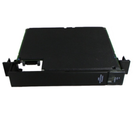
GE IC697CGR935 One Slot Controller Module
General info
| Manufacture | GE |
| Item No | IC697CGR935 |
| Article number | IC697CGR935 |
| Series | GE FANUC |
| Origin | United States(US) |
| Dimension | 180*180*30(mm) |
| Weight | 0.8 kg |
| Customs Tariff Number | 85389091 |
| Type | Controller Module |
Detailed data
GE IC697CGR935 One Slot Controller Module
The IC697CGR935 module in the Redundancy System is used as the controller. There are two control methods to note when using the IC697CGR935. In the GHS process, several single bus networks with one redundant controller are used in each synchronized PLC. When using the GDB process, multiple I/O networks are used with single or double buses in each synchronized PLC. Each control method can be easily activated and used without difficulty. In the IC697CGR935 module, the memory board delivers data, and program memory is included with the module. The IC697CGR935 can be operated remotely or by the three position RUN/STOP switch. Positioned on the front of the module are the LEDs, which specify the status of the CPU.
The key switch should be positioned to MEMORY PROTECT OFF, and there should be no rack power. Once module is installed in slot 1 of rack 0, power is turned on. The top LED should blink indicating that the IC697CGR935 module is powered up. Once the diagnostic is finished effectively, the top left LED stays on while the second and third LED will be off. The MEMORY PROTECT LED which is the fourth LED, is off because the key switch is in off position. Programming is now ready for the CPU. The CPU can be programmed regardless of the placement of the key. Once the program has been confirmed, the toggle switch can be positioned in the appropriate operational mode.